Is this the winning formula? Finally I have a balanced version that has multiple pressure input legible and allows emergent pattern. I have added a lock out that stops endless cycling after a reasonable time to see emergence (15 sec) if a low gate condition has been reached (lights on 3 times in that 15 sec). During a lock out period (10 sec) I imagine pressure input would result in a low buzz to indicate it was disabled.
I have kept the min off time to a minimum to maximise feedback from pressure input, and increased the flag delay and limited the max on time to ensure not all lights are on at the same time. Also I think mode 2, clockwise internal communication arrangement, is most coherent to use, because the communication between tiles is clockwise. Controls are still enabled - so keep playing!
Friday, July 15, 2011

Monday, May 30, 2011
D, I & E Tile Processing Mockup V2
Here is a revised version with controls to change variables so that everyone can have a bit of a play.
I have added the potential to set a minimum time that cells must be off before they can be turned on by neighbouring cells being on. This can be used to break the endless cycle and makes responses and interactions from simultaneous pressure sensor inputs at opposite sides of the board more legible. Unfortunately pressure sensor inputs can not be communicated to neighbouring cells that are serving a minimum time off (this is possible to code, but our physical communication setup can not differentiate the cause of neighbouring cells' lights being on). There is also then the potential to set a maximum time that cells can be off before they randomly turn themselves on.
I am not sure what the optimum arrangement is for our installation, and if it would be interesting or too unintelligible for each tile to have individual settings. So keep playing!
I have added the potential to set a minimum time that cells must be off before they can be turned on by neighbouring cells being on. This can be used to break the endless cycle and makes responses and interactions from simultaneous pressure sensor inputs at opposite sides of the board more legible. Unfortunately pressure sensor inputs can not be communicated to neighbouring cells that are serving a minimum time off (this is possible to code, but our physical communication setup can not differentiate the cause of neighbouring cells' lights being on). There is also then the potential to set a maximum time that cells can be off before they randomly turn themselves on.
I am not sure what the optimum arrangement is for our installation, and if it would be interesting or too unintelligible for each tile to have individual settings. So keep playing!
Sunday, May 29, 2011
D, I & E Tile Processing Mockup
Here is a quick Processing mockup of our current tile arrangement to demonstrate that lights are communicated in circles. I have also tested some alternative arrangements that produce various other emergent patterns, such as diagonal stripes, by communicating between cells within tiles. All of the arrangements produce endless loops from a single pressure sensor input, but unfortunately in all of the arrangements multiple pressure sensor inputs produce either no legible response or fairly uninteresting interactions.
Controls:
mouse click = pressure sensor input / footstep (to begin)
key q = turn all lights off
key 1 = only neighbouring tiles (current arrangement)
key 2 = neighbouring tiles plus internal cells clockwise
key 3 = neighbouring tiles plus internal cells anti-clockwise
key 4 = neighbouring tiles plus internal cells diagonal
key 5 = neighbouring tiles plus all internal cells
key 6 = neighbouring tiles plus internal cells horizontal
key 7 = neighbouring tiles plus internal cells vertical
Controls:
mouse click = pressure sensor input / footstep (to begin)
key q = turn all lights off
key 1 = only neighbouring tiles (current arrangement)
key 2 = neighbouring tiles plus internal cells clockwise
key 3 = neighbouring tiles plus internal cells anti-clockwise
key 4 = neighbouring tiles plus internal cells diagonal
key 5 = neighbouring tiles plus all internal cells
key 6 = neighbouring tiles plus internal cells horizontal
key 7 = neighbouring tiles plus internal cells vertical
Friday, May 27, 2011
D, I & E Reflection
A very big thank you to Stephen Barrass. I very much value the intensive delivery mode of the Digital Design technology units where I feel like I can quickly progress by implementing and then expanding upon learning immediately - before it can be forgotten and then require recapping as in other potential delivery modes. As with previous Digital Design units, Design, Interaction & Environment has opened up a whole new world.
I have never before played with electronics or microprocessors, let alone felt audacious enough to attempt an interactive installation. Of course with any newly learned skills I will need to keep practicing, and it can sometimes be difficult to find the initiative to do this - however I believe that the rapid progression through this unit will now make it more likely that I have the confidence to attempt a project of complexity sufficient to be inspiring. In fact, if I have time, I would like to set up an interactive installation for the my end of year architecture graduating exhibition, which tends to be well attended and a bit of a party.
A particularly appreciated learning experience I think was the production of an installation, which in many ways was a 'real' project. Group work can be very stimulating, but can in a University situation be more often than in a workplace challenging because of unclear roles, lack of (or competing) leadership and group members who don't pull their weight. Thankfully this unit, as a whole of class group project led and facilitated by Stephen, proved to be very productive, and group members who had diverse backgrounds were able to contribute in different ways.
The best bit of the realness of this project was that Stephen left in all the messy bits: we were able to develop a design direction collectively, which is not the easiest processes; we had to shop for the components and materials, which were not always available meaning that we had to adapt the design; we had to investigate and learn new fabrication technologies; and ultimately we ran out of time to finish within the intensive class time! All wonderful lessons in production.
So through this unit I learnt some technical skills like constructing simple electronic circuits and drawing circuit diagrams, and working with various potentiometers and a microprocessor. I also gained great confidence in the adaptability of my programming, particularly in learning Arduino code, which is slightly different to Processing, and in figuring out how to make a library when I was stuck trying to implement classes.
More importantly perhaps were considerations of pertinent content, meaningful interaction, and legible interfaces and environmental responses in the design of installations. Although we were only able to include in our project some of these design and theory ideas, and perhaps in a fairly limited way, I found the class discussion on background readings and research for project proposals most engaging and worthy of expansion in future classes.
I am looking forward to continuing to work on our installation over the next couple of months. I hope that it can still be somewhat collectively curatable - that is I think that more than one person will be able to fit on the tiles at the same time and so suggest that a focus should be interaction between responses to multiple footfalls.
The theme of exploring self organisation is also something that I have had an ongoing interest in. I like very much the tactility of seeing and interacting with self organising systems that are rendered outside of the computer screen.
Taking research at the intersection of self organising systems, architecture and physical computing to a conceptual extreme are R&Sie(n), whose project 'I've heard about' for example envisions an architecture not centrally controlled, self constructed and continually grown and adapted, by landscape secreting 'Viabs' which respond to local conditions including chemical emissions data of it's human inhabitants. This biostructure no longer seems quite so futuristic.
I have never before played with electronics or microprocessors, let alone felt audacious enough to attempt an interactive installation. Of course with any newly learned skills I will need to keep practicing, and it can sometimes be difficult to find the initiative to do this - however I believe that the rapid progression through this unit will now make it more likely that I have the confidence to attempt a project of complexity sufficient to be inspiring. In fact, if I have time, I would like to set up an interactive installation for the my end of year architecture graduating exhibition, which tends to be well attended and a bit of a party.
A particularly appreciated learning experience I think was the production of an installation, which in many ways was a 'real' project. Group work can be very stimulating, but can in a University situation be more often than in a workplace challenging because of unclear roles, lack of (or competing) leadership and group members who don't pull their weight. Thankfully this unit, as a whole of class group project led and facilitated by Stephen, proved to be very productive, and group members who had diverse backgrounds were able to contribute in different ways.
The best bit of the realness of this project was that Stephen left in all the messy bits: we were able to develop a design direction collectively, which is not the easiest processes; we had to shop for the components and materials, which were not always available meaning that we had to adapt the design; we had to investigate and learn new fabrication technologies; and ultimately we ran out of time to finish within the intensive class time! All wonderful lessons in production.
So through this unit I learnt some technical skills like constructing simple electronic circuits and drawing circuit diagrams, and working with various potentiometers and a microprocessor. I also gained great confidence in the adaptability of my programming, particularly in learning Arduino code, which is slightly different to Processing, and in figuring out how to make a library when I was stuck trying to implement classes.
More importantly perhaps were considerations of pertinent content, meaningful interaction, and legible interfaces and environmental responses in the design of installations. Although we were only able to include in our project some of these design and theory ideas, and perhaps in a fairly limited way, I found the class discussion on background readings and research for project proposals most engaging and worthy of expansion in future classes.
I am looking forward to continuing to work on our installation over the next couple of months. I hope that it can still be somewhat collectively curatable - that is I think that more than one person will be able to fit on the tiles at the same time and so suggest that a focus should be interaction between responses to multiple footfalls.
The theme of exploring self organisation is also something that I have had an ongoing interest in. I like very much the tactility of seeing and interacting with self organising systems that are rendered outside of the computer screen.
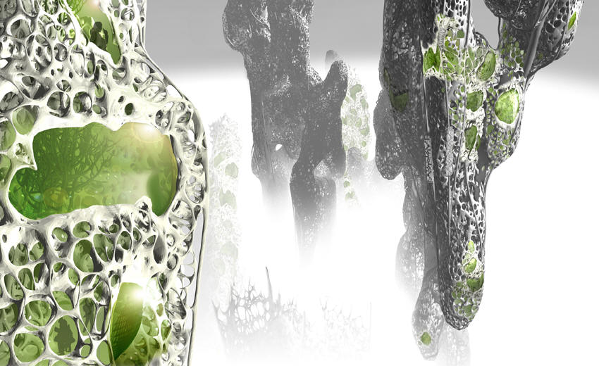 |
| R&Sie(n) 'I've heard about' |
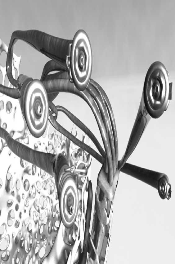 |
| R&Sie(n) 'I've heard about' |
Saturday, April 30, 2011
D, I & E Intensive 2 Day 3
We now have the projects substantially finished, but we didnt get to install them today or test how they interact or give them individualised behaviours. We will get together for another workshop in the holidays and do a test install then before the exhibition at the Belconnen Arts Centre. I suppose that is an important lesson in just how long all the little things take to get done, and how often things dont work smoothly as expected and so need resourceful on the spot thinking.
I do feel like I have come a long way in 6 days, and have confidence now to finish my tile myself - and then go on to do any other project on my own. I had never worked with electronics before this.
SOFTWARE
I wrote my first library! What a challenge - after spending the evening before adapting our code to classes as I would set them up in Processing, I spent almost the entire morning figuring out how to make them work in Arduino as a library.
Essentially Arduino is built on C++, which has similar syntax to Processing which is built on Java - but they are not the same or directly compatible. I will have to read up more about this. The previously linked to tutorial was very helpful and got the basic setup for me.
However after hours of debugging and browsing the Arduino forums I still had one unsolvable problem - I couldn't get the constructor to recognise instances of custom classes. I had made seperate led and light sensor eye classes, and was trying to get the led class to know about their own eye as well as the other 3 eyes in the tile. So I got around this by unifying the classes in a single cell class. Lesson - try to make two classes talk to each other at your own peril!
There are a few other key differences between this and a Processing implementation:
However I have tried to design the library to be flexibile so that for most of the things we might want to achieve with the tiles we shouldnt have to touch it. There are some global variables that can be updated via the cellSettings() function. I have added parameters to control the eye flag threshold for turning on/off the LEDs, change the delay between the eye flags and the LEDs turning on, and to set a minimum time that the LEDs have to be on before they can be turned off. I have also added a boolean switch to turn on/off the fade and a time step to lengthen the time it takes to fade.
There is lots that can be done from outside the library - for example the knob is hooked up to change the flag delay via the cellSettings() function and the buzzer is set up with all of it's parameters (frequency, duration etc) outside the library and is hooked up to make a tone when it recieves a toneSet signal which is sent when a cell turns on the lights in the function doLight(). The pressure sensor controls lights differently, outside of the library ( ie not in doLight() ), by simply setting brightVal to be 255. The LEDs can be set at anytime to be any gradient of brightness by changing brightVal.
Also I gave each of the cells specific names (topLeftCell, bottomRightCell etc) not because it matters which way the tile is oriented, but so that it would be easy to program communication between cells remembering which cell is clockwise or anticlockwise adjacent or diagonally opposite. Internal communication may need to be considered by the whole class because with the current code and physical circuit setup ripples will not propagate beyond the tiles immediately adjacent.
Anyway the main outcome that I was trying to achieve was robust base code that has plenty of room for others to develop some differentiated individual behaviors for their tiles.
HARDWARE
With limited materials we put together a couple of working protoypes. Richard Spellman and I worked together. There were a few issues that we met.
The red LEDs we have been using are not very strong so we are back to planning to seperate neighbour communication LEDs from display lighting. However we have almost run out of pins on our Arduino microprocessor - there are still a few digital pins, but these can only be ON or OFF. The breadboard is also very busy and we ran out of wires so have confused colours (eg we put the knob on the output side and used black, blue and white wires for ground). It would be nice to have multiple breadboards, and particularly breadboards with positive and ground rails (this would save a lot of wiring).
The piezo pressure sensor creates it's own current so doesnt need connecting to positve. It needs to be wired accross a resistor to register differences in current and we had to change to a 1 mega ohm resistor so that it would be more sensitive. The piezo only creates a tiny amount of electricity so we need a big resistor to draw out the time it takes for it to flow to ground. The piezo we are using is salvaged from a piezo speaker.
Each light sensor responds markedly differently and so will need individual calibration. Also we need to consider if we want to access the knob from outside of the tile casing.
When we setup the circuit in the casing we will need longer wires for neighbour communication light sensors and LEDs, and perhaps other things too, and not everything will be on a bread board. We will have to be careful fixing components down and will need to remember to case exposed wires so they dont short circuit.
We still need to test the audibility of the buzzer through the acrylic and whether we need some pin holes. We also have to prototype different display LED configurations to test the brightness and how they display through different backing sheets, patterns etc - this is something that we will each be doing now individually.
Also an over site - full credits for the project! Our lecturer is Stephen Barrass and the class is Vanessa Wang, Anaer Anaer, Nathan Evans, Subyeal Pasha, Natalia Lopez, Amber Standley, Richard Spellman and myself.
I do feel like I have come a long way in 6 days, and have confidence now to finish my tile myself - and then go on to do any other project on my own. I had never worked with electronics before this.
SOFTWARE
I wrote my first library! What a challenge - after spending the evening before adapting our code to classes as I would set them up in Processing, I spent almost the entire morning figuring out how to make them work in Arduino as a library.
 |
| Code with library header and class files in foreground |
However after hours of debugging and browsing the Arduino forums I still had one unsolvable problem - I couldn't get the constructor to recognise instances of custom classes. I had made seperate led and light sensor eye classes, and was trying to get the led class to know about their own eye as well as the other 3 eyes in the tile. So I got around this by unifying the classes in a single cell class. Lesson - try to make two classes talk to each other at your own peril!
There are a few other key differences between this and a Processing implementation:
- the code is written in separate files that are saved in the libraries directory of the Arduino install directory (Arduino/libraries) and edited in a text editor such as notepad, these are:
- Cell.cpp, the class file where all the code goes
- Cell.h, a header file which is like a contents
- keywords.txt, a list of keywords to highlight the code in Arduino
- there is additional wrapping syntax before the constructor and other functions in the class file (ie Cell : : )
- there must be a link to the standard Arduino library (ie #include "WProgram.h" ) and any other libraries you are using (if you can get them to interface!)
- the header file lists the constructor and all the parameters and functions, so is a handy reference to remember the names you can call - public functions and parameters can be called, manipulated, updated etc in the same way as you would with Processing classes - private functions and parameters can only be called from within the class
- in your Arduino code you need to import the library (ie #include <Cell.h> ) and remember to restart Arduino to get it to recognise a new library
However I have tried to design the library to be flexibile so that for most of the things we might want to achieve with the tiles we shouldnt have to touch it. There are some global variables that can be updated via the cellSettings() function. I have added parameters to control the eye flag threshold for turning on/off the LEDs, change the delay between the eye flags and the LEDs turning on, and to set a minimum time that the LEDs have to be on before they can be turned off. I have also added a boolean switch to turn on/off the fade and a time step to lengthen the time it takes to fade.
There is lots that can be done from outside the library - for example the knob is hooked up to change the flag delay via the cellSettings() function and the buzzer is set up with all of it's parameters (frequency, duration etc) outside the library and is hooked up to make a tone when it recieves a toneSet signal which is sent when a cell turns on the lights in the function doLight(). The pressure sensor controls lights differently, outside of the library ( ie not in doLight() ), by simply setting brightVal to be 255. The LEDs can be set at anytime to be any gradient of brightness by changing brightVal.
Also I gave each of the cells specific names (topLeftCell, bottomRightCell etc) not because it matters which way the tile is oriented, but so that it would be easy to program communication between cells remembering which cell is clockwise or anticlockwise adjacent or diagonally opposite. Internal communication may need to be considered by the whole class because with the current code and physical circuit setup ripples will not propagate beyond the tiles immediately adjacent.
Anyway the main outcome that I was trying to achieve was robust base code that has plenty of room for others to develop some differentiated individual behaviors for their tiles.
HARDWARE
 |
| Concept diagram showing neighbour communication paths |
 |
| Circuit diagram showing inputs on left and outputs on right |
The red LEDs we have been using are not very strong so we are back to planning to seperate neighbour communication LEDs from display lighting. However we have almost run out of pins on our Arduino microprocessor - there are still a few digital pins, but these can only be ON or OFF. The breadboard is also very busy and we ran out of wires so have confused colours (eg we put the knob on the output side and used black, blue and white wires for ground). It would be nice to have multiple breadboards, and particularly breadboards with positive and ground rails (this would save a lot of wiring).
The piezo pressure sensor creates it's own current so doesnt need connecting to positve. It needs to be wired accross a resistor to register differences in current and we had to change to a 1 mega ohm resistor so that it would be more sensitive. The piezo only creates a tiny amount of electricity so we need a big resistor to draw out the time it takes for it to flow to ground. The piezo we are using is salvaged from a piezo speaker.
Each light sensor responds markedly differently and so will need individual calibration. Also we need to consider if we want to access the knob from outside of the tile casing.
When we setup the circuit in the casing we will need longer wires for neighbour communication light sensors and LEDs, and perhaps other things too, and not everything will be on a bread board. We will have to be careful fixing components down and will need to remember to case exposed wires so they dont short circuit.
We still need to test the audibility of the buzzer through the acrylic and whether we need some pin holes. We also have to prototype different display LED configurations to test the brightness and how they display through different backing sheets, patterns etc - this is something that we will each be doing now individually.
 |
| A working prototype Richard Spellman and I put together |
 |
| The prototype as it fits in the casing - the pressure sensor will sit in the middle just under the acrylic tile, and LEDs and light sensors will be in each cell |
 |
| Some longer wires for the LEDs and light sensors prepared by Richard |
 |
| Stephen Barrass, Natalia Lopez and Nathan Evans drilling the casing together |
Friday, April 29, 2011
D, I & E Intensive 2 Day 2
10AM
In thinking about the design approach to my tile, I have tried to establish a hierarchy of inputs and outputs to assist clarity.
The primary input I think is the pressure sensor (a footstep) as this is the direct interactive input from the audience, so output responses to this should be dominant over other outputs - and immediate. Probably all responses to inputs should be fairly immediate, else they loose legibility. So therefore responses have to either be short, additive or interruptible - rather than queued.
There are 4 neighbour communication channels (inputs/outputs). These must be treated equally I think so that the tile is robust enough to be placed anywhere. For example if a tile is placed in the bottom right corner where it has no right neighbour then it would be silly to have a response behaviour that can only be turned on with a signal from the right and equally it would be silly to try to pass output signals only to the right. Therefore I think that all neighbour outputs should always be the same signal and that the relevant neighbour input signal states are limited to: 'I am recieveing a signal from a neighbour', 'I am recieving a signal from more than 1 neighbour', 'I am not recieving a signal from a neighbour' and 'I have not recieved a signal from a neighbour for x period of time'. In a 9 square grid - 3x3 - there is 1 centre square that has 4 neighbours, 4 squares that have 3 neighbours and 4 corner square that have 2 neighbours.
Outputs are a bit of a balancing act - between variety of responses and legibility. I could have simply on/off, which might be a bit boring (?) but very clear. At the other extreme, given that we are using analogue signals, I could have continuous gradients to give numerous variations (0-255), but these would likely be harder to distinguish. I am leaning toward steps - perhaps 3-5 to be determined by protyping (eg 3 steps would be LOW: 0-85, MID: 85-170 and HIGH: 171-255).
The output responses will be various combinations of light and sound, including varied brightness, blinking, delays, duration, and frequency, and may be thought of as calls that can be made once or perhaps repeated in a pattern.
For example:
That is already 9 different behaviours - at least 6 calls - perhaps even this is too much for clarity?
12PM
Stephen has suggested that as our casing has four quads that we design four pixels per tile. So visually our grid will be 9 square super cells and 36 square sub cells (6x6). We are now planning on passing out different signals on each side (regardless of whether a neighbour exists on that side) and having each pixel behave individually.
Stephen is keen that we first set up all of the tiles to behave in the same coherent way - that is is you step on a tile all four of it's pixels turn on, and then pixels in neighbouring tiles ripple on (each pixel turns on after a second delay if its neighbouring pixel is on). Each pixel has two sides (potentially two neighbours) and only recieves signals from one neighbour and only passess signals to the other neighbour (because each tile has four light sensors and four pixels) - this means that communication paths will be quite particular through the grid.
Stephen has also suggested that we dont need seperate LEDs for communication with neighbours - that leaked light from our diplay LEDs should be sufficient to register differences with the light sensors. We will prototype this and see. The great benefit of less LEDs is that is simplifies our wiring - and we only have limited breadboard space and particularly limited input/output pins on the Arduino microprocessor. We are also concerned that the little red LEDs that we are prototyping with wont be bright enough to make the display engaging - we will have to wait and see how it all comes together tomorrow. We will be able to make changes before the exhibition in Belconnen.
5PM
An update on fabrication - we collected the materials (and learnt how to tie knots to secure them to the roof of the car) and began getting the ply CNC routed in the workshop. The router doesnt cut all the way through so that pieces can be held together stably. Kudos to Nathan Evens who led documentation and supervision of the routing.
The acrylic was already cut into 38cm squares for us by Plastic Creations and the ply came from Mitchell Building Supplies as Bunnings Warehouse doesnt keep 25mm ply in stock. We also picked up some non-slip rubber underlay from Clark Rubber.
While I had been working in the fabrication team Vanessa Wang, Anaer Anaer, Subyeal Pasha and Natalia Lopez had been leading development of the code.
12AM
This evening I was trying to tidy our code with classes but found that they dont behave the same way as in Processing and in fact need to be set up as libraries. Perhaps I can try to implement this tomorrow.
I was also experimenting with different ways to make lights fade off - for example our first code dimmed the brightness by 1 each loop (255 = on, 0 = off). A loop might take up to 15 milliseconds if there is lots of code and I didnt want to change from integers to longs - so my ideas for lengthening the fade time were to either have a counter each loop and only every nth count dim the brightness by 1 or to have a time step and only dim the brightness by 1 after each time step had passed. I went with the time step because I thought it would be more accurate.
Also I was thinking about allowing internal communication via code between the four pixels in a tile about their state (on, off etc).
In thinking about the design approach to my tile, I have tried to establish a hierarchy of inputs and outputs to assist clarity.
The primary input I think is the pressure sensor (a footstep) as this is the direct interactive input from the audience, so output responses to this should be dominant over other outputs - and immediate. Probably all responses to inputs should be fairly immediate, else they loose legibility. So therefore responses have to either be short, additive or interruptible - rather than queued.
There are 4 neighbour communication channels (inputs/outputs). These must be treated equally I think so that the tile is robust enough to be placed anywhere. For example if a tile is placed in the bottom right corner where it has no right neighbour then it would be silly to have a response behaviour that can only be turned on with a signal from the right and equally it would be silly to try to pass output signals only to the right. Therefore I think that all neighbour outputs should always be the same signal and that the relevant neighbour input signal states are limited to: 'I am recieveing a signal from a neighbour', 'I am recieving a signal from more than 1 neighbour', 'I am not recieving a signal from a neighbour' and 'I have not recieved a signal from a neighbour for x period of time'. In a 9 square grid - 3x3 - there is 1 centre square that has 4 neighbours, 4 squares that have 3 neighbours and 4 corner square that have 2 neighbours.
Outputs are a bit of a balancing act - between variety of responses and legibility. I could have simply on/off, which might be a bit boring (?) but very clear. At the other extreme, given that we are using analogue signals, I could have continuous gradients to give numerous variations (0-255), but these would likely be harder to distinguish. I am leaning toward steps - perhaps 3-5 to be determined by protyping (eg 3 steps would be LOW: 0-85, MID: 85-170 and HIGH: 171-255).
The output responses will be various combinations of light and sound, including varied brightness, blinking, delays, duration, and frequency, and may be thought of as calls that can be made once or perhaps repeated in a pattern.
For example:
- Pressure LOW > Response 1 (OFF)
- Pressure MID > Response 2
- Pressure HIGH > Response 3
- Neighbours ALL LOW > Response 4 (OFF)
- Neighbours ALL LOW for x time > Response 5
- Neighbours 1 x MID > Response 6
- Neighbours 1 x HIGH or 2+ x MID > Response 7
- Neighbours 1 x HIGH & 1+ x MID > Response 8
- Neighbours 2+ x HIGH > Response 9
That is already 9 different behaviours - at least 6 calls - perhaps even this is too much for clarity?
12PM
Stephen has suggested that as our casing has four quads that we design four pixels per tile. So visually our grid will be 9 square super cells and 36 square sub cells (6x6). We are now planning on passing out different signals on each side (regardless of whether a neighbour exists on that side) and having each pixel behave individually.
Stephen is keen that we first set up all of the tiles to behave in the same coherent way - that is is you step on a tile all four of it's pixels turn on, and then pixels in neighbouring tiles ripple on (each pixel turns on after a second delay if its neighbouring pixel is on). Each pixel has two sides (potentially two neighbours) and only recieves signals from one neighbour and only passess signals to the other neighbour (because each tile has four light sensors and four pixels) - this means that communication paths will be quite particular through the grid.
Stephen has also suggested that we dont need seperate LEDs for communication with neighbours - that leaked light from our diplay LEDs should be sufficient to register differences with the light sensors. We will prototype this and see. The great benefit of less LEDs is that is simplifies our wiring - and we only have limited breadboard space and particularly limited input/output pins on the Arduino microprocessor. We are also concerned that the little red LEDs that we are prototyping with wont be bright enough to make the display engaging - we will have to wait and see how it all comes together tomorrow. We will be able to make changes before the exhibition in Belconnen.
5PM
An update on fabrication - we collected the materials (and learnt how to tie knots to secure them to the roof of the car) and began getting the ply CNC routed in the workshop. The router doesnt cut all the way through so that pieces can be held together stably. Kudos to Nathan Evens who led documentation and supervision of the routing.
 |
| CNC router - showing different profile routs and cuts |
While I had been working in the fabrication team Vanessa Wang, Anaer Anaer, Subyeal Pasha and Natalia Lopez had been leading development of the code.
12AM
This evening I was trying to tidy our code with classes but found that they dont behave the same way as in Processing and in fact need to be set up as libraries. Perhaps I can try to implement this tomorrow.
I was also experimenting with different ways to make lights fade off - for example our first code dimmed the brightness by 1 each loop (255 = on, 0 = off). A loop might take up to 15 milliseconds if there is lots of code and I didnt want to change from integers to longs - so my ideas for lengthening the fade time were to either have a counter each loop and only every nth count dim the brightness by 1 or to have a time step and only dim the brightness by 1 after each time step had passed. I went with the time step because I thought it would be more accurate.
Also I was thinking about allowing internal communication via code between the four pixels in a tile about their state (on, off etc).
Wednesday, April 27, 2011
D, I & E Intensive 2 Day 1
So begins the second intensive for Design, Interaction & Environment. The first intensive we were learning basic skills for Arduino and making some prototype critters that could sense, respond to and influence their environment. This social colony of things were able to interact with their neighbours and displayed some emergent behavior patterns. In this second intensive we are focusing on production of an installation, first for the foyer of Building 9 at the University of Canberra and then perhaps as part of an exhibition in July at the Belconnen Arts Centre.
We spent the morning discussing ideas for the installation and came to a first concept that everyone could develop an individual critter that received environmental input in different ways (laser beam broken, pressure pad in cushion, strokable grass, noise level, Theremin proximity sensor, helium balloons that pull flex sensors, Xbox Kinect movement sensor etc) but was tied together by producing a single note in a coherent soundscape in similar fashion to the ToneMatrix.
We visited the site and found that it was possible to hide things under the terrain/seat (we discovered spiders and dead mice) or behind the acoustic ceiling tiles, and that if we had things that were not too heavy we could velcro them to the green carpet roof/wall or hang them from the light fittings, but that there were not many other places we could safely attach critters. We discussed linking a visualisation on the tv screens and even broadcasting this or a camera feed voyeuristically to other tv screens around the building, and also determined that it would be possible to transmit data by the building's network and so keep our laptops if needed in the server room.
In the afternoon we set about designing the standard shared hardware and casings. Every tile will have the same case, the same pressure sensor, and the same neighbour communication channels (LED out, light sensor in) to ensure that they robustly fit together and can be tiled in different positions.
We visited the workshop and learnt about using the new fabrication facilities at the University of Canberra - how to set up drawings, that the CNC router can cut sheets up to 25mm deep and 1200mm wide, that routing paths can be set for inside or outside of shape edges and to any depths, and that the laser cutter can engrave by reducing the beam intensity but that depending on the material this will be to different depths.
The casings will be 38cm square routed ply with acrylic tops. The hollowed ply will have spaces for the Arduino microprocessor, a battery (we might later try to hook up a power plug) and multiple bread boards (we want to keep the sensors and neighbour interface separate from the light and sound outputs), while maintaining structural support for the acrylic at the sides and centre.
We can get small piezo pressure sensors cheaply - they are a crystalline structure that produce a small current when pressed. The pressure sensor will be placed at the centre of the tile immediately below the acrylic where it will register even visually imperceptible bowing of the acrylic when stepped on.
We will probably use clear acrylic, meaning that individual design decisions in addition to how many LEDs to have, where to place them and how to program them also will include whether to frost or etch the acrylic or back it with translucent paper.
Tomorrow we will finalise the design of the casing and fabricate it. Hopefully we will have some time to design the content too, because the next day we plan to install!
We spent the morning discussing ideas for the installation and came to a first concept that everyone could develop an individual critter that received environmental input in different ways (laser beam broken, pressure pad in cushion, strokable grass, noise level, Theremin proximity sensor, helium balloons that pull flex sensors, Xbox Kinect movement sensor etc) but was tied together by producing a single note in a coherent soundscape in similar fashion to the ToneMatrix.
We visited the site and found that it was possible to hide things under the terrain/seat (we discovered spiders and dead mice) or behind the acoustic ceiling tiles, and that if we had things that were not too heavy we could velcro them to the green carpet roof/wall or hang them from the light fittings, but that there were not many other places we could safely attach critters. We discussed linking a visualisation on the tv screens and even broadcasting this or a camera feed voyeuristically to other tv screens around the building, and also determined that it would be possible to transmit data by the building's network and so keep our laptops if needed in the server room.
Ultimately however we decided to flip the first concept and make a unified input, as a tiled floor with pressure sensors and our critters under each tile, and have individual, divergent outputs in the form of light and sound. This will essentially be a tidier version of our social colony of things from the first intensive, with the critters still responding to neighbour states but with a more robust communication channel (better aligned, secured and calibrated LEDs and light sensors). The installation will behave and be structured much like a cellular automaton and will feel something like Dance Dance Revolution or the floor of the night club in Saturday Night Fever. As with the critters in the first intensive the light and sound outputs will probably be more of a cacophony than a symphony, but hopefully there will be coherent emergent patterns perceptible.
We visited the workshop and learnt about using the new fabrication facilities at the University of Canberra - how to set up drawings, that the CNC router can cut sheets up to 25mm deep and 1200mm wide, that routing paths can be set for inside or outside of shape edges and to any depths, and that the laser cutter can engrave by reducing the beam intensity but that depending on the material this will be to different depths.
 |
| Stephen Barrass workshopping the casing design |
We can get small piezo pressure sensors cheaply - they are a crystalline structure that produce a small current when pressed. The pressure sensor will be placed at the centre of the tile immediately below the acrylic where it will register even visually imperceptible bowing of the acrylic when stepped on.
We will probably use clear acrylic, meaning that individual design decisions in addition to how many LEDs to have, where to place them and how to program them also will include whether to frost or etch the acrylic or back it with translucent paper.
Tomorrow we will finalise the design of the casing and fabricate it. Hopefully we will have some time to design the content too, because the next day we plan to install!
Subscribe to:
Posts (Atom)