Showing posts with label geometry. Show all posts

Tuesday, April 26, 2011

Hyperbolic Coral

This post is some long overdue documentation for the Hyperbolic Coral, which was the result of a computational nature study that Kerrin Jefferis and I did for the unit 8195 Generative Design and was exhibited last November as part of Cultural Interfaces at CraftACT.

The idea of a computational nature study was to develop a generative system based on an understanding of the logic of a natural system, a practice that has been gaining momentum in architecture. In nature there are many examples of hyperbolic forms including those found in kelps, anemones and corals as well as sea slugs and leaves from lettuce to holly. Hyperbolic geometry is non-Euclidean, having at least two lines parallel to any line l through any point A not on l, and is characterised by maximised, exponentially increasing, surface area and boundary edge length. Coral needs maximised surface to collect nutrients from the sea, while sea slugs use it to propel themselves with minimal effort.

The starting point of the project was an inspiring TED lecture by Margaret Wertheim about her Crotchet Coral Reef project with the Institute for Figuring which has seen satellite reefs crocheted all around the world. We fairly literally made a digital version of this system in Processing using the Traer Physics simulation library.


Crotchet Coral and Anemone Garden with Sea Slug, Marianne Midelburg (photo: Alyssa Gorelick)

Crotchet was first used to model hyperbolic forms by Daina Taimina in 1997. Other mathematics had been struggling to model hyperbolic forms for decades. The genius of the approach is that it doesn't require a complex mathematical description of the entire form - just a simple algorithm describing the relationship between one row of stitches and the next. Normally in crotchet new rows have one stitch for each stitch in the previous row. However with hyperbolic crotchet an extra stitch is added for every nth stitch in the previous row. We have termed this a growth pattern, and conceptually thought about the coral growing from the first row.

To translate the system to Processing we needed two conceptual parts - a constructor to build relationships between stitches and a physics simulator to give material properties allowing the stitches to self optimise their position (ruffle).

Essentially the stitches are replaced with particles connected by springs. The particles are free to move and the springs can be compressed or stretched but have a rest length that they try to reach. The system comes to equilibrium when as many springs are as close as possible to their rest length - a condition that requires a resolved hyperbolic form.

The constructor takes a ring with x particles and grows i rings based on a growth pattern (eg {1,2} specifies an extra particle for every 2nd particle in the previous ring). The particles are connected by springs to the immediately adjacent particles in the ring and to the parent particle in the previous ring.

Hyperbolic Coral - {2,3} growth pattern, 4 particles in first, 5 rings 

Hyperbolic Coral - {3,3} growth pattern, 4 particles in first, 5 rings

Particle physics simulation is computationally resource intensive limiting the number of particles that a model can contain. A coarse polygon mesh makes a perceptually faceted model. We smoothed our model, approximating the form of a model with more rings of particles by exponentially increasing the rest length of springs between outer rings.

A repellent force between all particles was introduced to assist the form finding - where as fabrics have a certain stiffness this system could bend back on itself 'impossibly' and get tangled up. Additional springs could be added as cross-bracing to further reduce bending.

To ensure a stable system the strengths of all the forces including drag and spring stiffness and damping need to be continually tweaked for each change in the number and density of particles (controlled with variables such as number of particles in the first ring, growth pattern, number of rings and spring rest lengths). This constant micro management of the system doest allow a single stable profile to be set such that a 'plug and play' generic hyperbolic form generator can be sent out into the world. The version on Open Processing is stable for the range of: 5 rings; growth patterns {2,3} to {3,5}; and 4, 6 or 8 particles in the first ring.
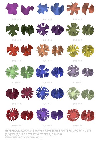
Hyperbolic Coral - the full set of possible models from the Open Processing version
We had a go at fabricating a model using Shapeways nylon selective laser sintering (SLS). A polygon mesh was exported from Processing to Rhino where it was cleaned up, thickened into a volume 1.5mm thick and saved as an STL file for Shapeways.

Hyperbolic Coral - nylon SLS
Coral hanging out at Cultural Interfaces with Mitchell Whitelaw's Weather Bracelet and Measuring Cup
(photo: Mitchell Whitelaw)
Once released into the wild some renderings of the coral popped up at architectural scale visualising the potential for a giant pavilion! In terms of architectural application I mostly imagine continuing the exploration of self organising/optimising systems and training these for architectural purpose. A very beautiful realised installation is Chris Bosse's Green Void, which is a hyperbolic form with a different generating strategy. Of course one can also imagine functional reasons for wanting hyperbolic forms given they have exponential surface and boundary.

Hyperbolic Coral  in the wild (rendering: Dominik Raskin)
Hyperbolic Coral in the wild (rendering: Dominik Raskin)
In the future it would be nice to train the coral generator to do more tricks including accommodating different starting geometry and multiple pieces that can be stitched together. The Crotchet Coral Reef project encourages participants to introduce mutations into their algorithms to create endless variations (evolutions) that are not mathematically pure, which I suspect is a rich strategy for future exploration.

Monday, December 13, 2010

Reflections on Generic City

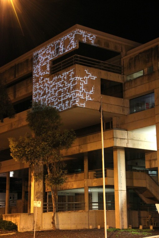
Performance night was successful and a lot of fun (see photos following). Many thanks to Mitchell Whitelaw for organising the project and superb guidance throughout.

Generic City C8 - performance night, photographer Mitchell Whitelaw
Not such a generic audience...
Picnic rug on kerb side?
Refining after the dry run, I developed a tool to set, remember and edit where windows are, and so was able to make growth avoid windows. This worked very smoothly (although it was a little cumbersome to edit using arrow keys) and was a great visual improvement on the untidiness of the dry run. 

Also after the dry run, I slowed the growth rate and increased the range of growth speeds, but perhaps could have gone further - I was trying to balance against speed to show at a glance the dynamic and iterative quality. On the night in response to feedback I did in fact slow it down further. Mitchell described the generated cities as having an elusive quality - just as soon as they were fully grown they disappeared, and because you never knew when they were fully grown and therefore about to disappear, it was impossible to photograph! Mitchell's very nice suggestion was to pause before disappearing and then fade in transition. 

This got me thinking about other ways to improve legibility. As each frame many cells can grow and as each cell can have many children or branches, it quickly becomes difficult to follow new growth. Perhaps I could have more tightly controlled growth by keeping track of a cell's age since it last grew and limiting future growth in this way, or by limiting number of children or branching so that growth is more linear - I didnt consider limiting branching previously because I was only thinking about density which I controlled by number of neighbours.

Further it might be interesting to trace pathways through the city or highlight precincts defined for example by blocks serviced by particular streets, blocks adjoining particular public squares or neighborhoods of the same block type. This would assist in reading the structure of the city.

On the performance night it was again abundantly clear that the simplest geometries were the most striking and legible at this scale. Perhaps, against what I wrote previously, this is cause to extend a shape grammar with little variance and highly structured relationships endlessly across the facade. Perhaps a Cameron Offices or other John Andrews skin, or even a skin based on the Nolli Plan of Rome would have been really effective. This is a lesson about misjudgment, a reminder to test often and early.

The most significant difference between Generic City and a potential John Andrews shape grammar is that Generic City has non-deterministic relationships adding an exciting additional layer of complexity - that of allowing emergent orders, simply from interactions between neighbouring cells. Harnessing emergence better simulates organic city growth, accommodating multiple competing forces, and so makes for the beginnings of a potentially powerful analytical or design tool.

One final loose end, I previously suggested making Generic City interactive. I never pursued this because I judged that apart from conditions that changed the speed of growth or events that terminated a city and began a new one it would be difficult to make the interactivity legible - what condition could legibly control block type for instance? Further any interaction would potentially clash with internal growth imperatives, making the underlying system more difficult to read.

This project is principally concerned with exploring a generative system and grounding it by the interpretive content: tectonic dressing of structure, articulating surface and fenestration; generative system as emphasis of the architecture as system; networked city precinct to reveal the seeds for a greater whole contained within a single building; an iterative production to imply the conflation of past, future and alternate realities. It is critical that the system is legible.

Generic City C8 - performance night, photographer Mitchell Whitelaw

Extending John Andrews - a shape grammar?

One part of my early proposal, that I have mulled over for sometime but never pursued, was for a generative cityscape that remixed the geometry of Cameron Offices and other John Andrews or exemplar modern architectures. 

I created a Generic City and continued refining it, while holding off on fitting a  shape grammar to it as a skin. While it should be possible with a small amount of adaption to plug in almost any simple geometry (including non-orthogonal geometry by switching back to an 'off-lattice' Eden Growth Model which would require a different method of locating neighbouring cells), I felt that a shape grammar skin could be deterministic with highly structured relationships and that the open-ended further abstracted generic geometry was perhaps more robust in generating differentiation.

When for example I was considering a shape grammar for the Cameron Offices, I was immediately stuck with a couple of problems. All of the offices are oriented E-W to reduce direct sunlight (early morning / late afternoon). If I was to extend this endlessly it would be pretty boring - monotonous. This is the first problem - that Andrews did not design for variation: he designed in fixed modules (in a time before the changed economies of digital fabrication). Perhaps it would have been interesting to abstract further John Andrews grammar and introduce limited variance - but would this be true to Andrews? Probably I should have conceived this as an updating of his geometry appropriate for this time, that could be true if it didnt break any fundamental rules - whatever they might be. For example maybe I could decide that E-W orientation is not fundamental, but shading is - however if I introduced N-S orientation then I would have to design new shading and a way of turning corners. This is the second problem, I would have to design - the Cameron Offices does not have all of the information required for a shape grammar of an entire city, it is only a piece. 

Andrews clearly understood his projects as systems or networks, designing them to be extended and connected with other projects. However the extensions he considered, for example the Bellmere Public School (see below), were a couple of additional modules. Andrews I doubt would intend the same geometry, even with minor variance, to be extended endlessly - particularly across different programs. This is made clear with the interface/connections at the boundaries of the Cameron Offices where Andrews designed pedestrian bridges to connect with housing but did not indicate any geometry or even massing for the housing, and further where he did sketch a town square and retail centre adjacent on the North the geometry is manifestly distinct. This principle is further reinforced later by the Bus Interchange where Andrews makes the pedestrian circulation circular tubes - a more obvious contrast to the adjacent Cameron Offices is not imaginable.

John Andrews, Cameron Offices, site plan from 'Australian Architecture Since 1960', 2nd Edition, 1990, Jennifer Taylor

John Andrews, Cameron Offices and Belconnen Bus Interchange, Canberra,  photo from 'John Andrews: Architecture a Performing Art' 1982, Jennifer Taylor & John Andrews
Andrews shows how to make connections (pedestrian bridges), but as to what to connect to - well this could be almost any geometry. To illustrate the variety of Andrews geometries, and as a reminder of how significant an architect he has been, following is a selection of potential shape grammar seeds. Ultimately I felt that if I was designing I wanted it to be legible that it was my hand not Andrews and so I stayed with the generic geometry. Of course in the sense that Generic City is a system it is still closely associated with Andrews.

John Andrews, Scarborough College, University of Toronto, plan from 'John Andrews: Architecture a Performing Art' 1982, Jennifer Taylor & John Andrews
John Andrews, Scarborough College, University of Toronto, photo from 'John Andrews: Architecture a Performing Art' 1982, Jennifer Taylor & John Andrews
John Andrews, Bellmere Public School, Toronto, plan from 'John Andrews: Architecture a Performing Art' 1982, Jennifer Taylor & John Andrews
John Andrews, Bellmere Public School, Toronto, elevation from 'John Andrews: Architecture a Performing Art' 1982, Jennifer Taylor & John Andrews
John Andrews, Guelph University (Ontario) student residences, plan from 'John Andrews: Architecture a Performing Art' 1982, Jennifer Taylor & John Andrews
John Andrews, Guelph University (Ontario) student residences, photo from 'John Andrews: Architecture a Performing Art' 1982, Jennifer Taylor & John Andrews
John Andrews, African Place, Expo '67, axonometric plan from 'John Andrews: Architecture a Performing Art' 1982, Jennifer Taylor & John Andrews
John Andrews, African Place, Expo '67, photo from 'John Andrews: Architecture a Performing Art' 1982, Jennifer Taylor & John Andrews
John Andrews, Miami Port Passenger Terminal, section diagram from 'John Andrews: Architecture a Performing Art' 1982, Jennifer Taylor & John Andrews
John Andrews, Miami Port Passenger Terminal, photo from 'John Andrews: Architecture a Performing Art' 1982, Jennifer Taylor & John Andrews
John Andrews, The Canadian National (CN) Tower,  Toronto, photo from 'John Andrews: Architecture a Performing Art' 1982, Jennifer Taylor & John Andrews
John Andrews, Gund Hall studios, Harvard Graduate School of Design, photo from 'John Andrews: Architecture a Performing Art' 1982, Jennifer Taylor & John Andrews
John Andrews, Gund Hall studios, Harvard Graduate School of Design, section from 'John Andrews: Architecture a Performing Art' 1982, Jennifer Taylor & John Andrews
John Andrews, King George Tower, Sydney, photo from 'John Andrews: Architecture a Performing Art' 1982, Jennifer Taylor & John Andrews
John Andrews, Toad Hall student residences, Australian National University (ANU), plan from 'John Andrews: Architecture a Performing Art' 1982, Jennifer Taylor & John Andrews


John Andrews, Toad Hall student residences, Australian National University (ANU), photo from 'John Andrews: Architecture a Performing Art' 1982, Jennifer Taylor & John Andrews
John Andrews, New Res student residences, University of Canberra, unit plan from 'John Andrews: Architecture a Performing Art' 1982, Jennifer Taylor & John Andrews


John Andrews, New Res student residences, University of Canberra, photo from 'John Andrews: Architecture a Performing Art' 1982, Jennifer Taylor & John Andrews
John Andrews, Callum Offices, Woden, Canberra, site plan from 'John Andrews: Architecture a Performing Art' 1982, Jennifer Taylor & John Andrews
John Andrews, Callum Offices, Woden, Canberra, photo from 'John Andrews: Architecture a Performing Art' 1982, Jennifer Taylor & John Andrews
John Andrews, House at Eugowra (near Parkes), NSW, photo from 'John Andrews: Architecture a Performing Art' 1982, Jennifer Taylor & John Andrews

Sunday, December 12, 2010

Interpretation key to projection success

I have previously said that I felt that projections that a have a critical content closely associated with place and/or are tightly configured to the tectonic of the surface projected onto are more successful - ie that the layer they add to a place is principally interpretive and that this therefore should be an important frame in their critique.

An old favourite of mine is Scott Snibbe's voronoi Boundary Functions - an interactive projection that mapped personal space. This has often been in my mind as a benchmark - interactive and interpretive, with a legible tectonic closely related to the voronoi system at a human scale. The voronoi diagram is highly suited to this purpose - it is simply a boundary drawn perpendicular halfway between points (the points are people in this case).

Scott Snibbe, Boundary Functions 
Following are two student projects included in Output 09 that are variations on this theme. Frederic Eyl, Gunnar Green and Richard The's Sonderzug is a proposal to remember, as a ethereal trace, trains that deported Jewish people to ghettos, while Oliver Ellger and Jeffrey Gold's Ipunkt is a proposal for a fairly impractical personal navigation device for museums and galleries.

Frederic Eyl, Gunnar Green and Richard The, Sonderzug - ghetto destination projected from Berlin bridge
Frederic Eyl, Gunnar Green and Richard The, Sonderzug - ghost train
Oliver Ellger and Jeffrey Gold, Ipunkt

Sunday, December 5, 2010

Generic City - dry run

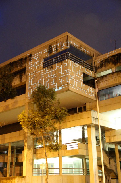
Here are some photos from this weeks dry run. Everything seemed to work pretty well, and we even caused enough interest to almost cause a couple of passing cars to crash. David Bouchard's Keystone library for Processing worked a treat - it was easy to accurately map to the building. Two issues however became apparent.

Generic City C6 - dry run, photographer Mitchell Whitelaw
The first is that growth was too fast - this is a quick fix. My perspective seeing Generic City close up on a screen and having an intimate knowledge of the geometry is significantly different to someone viewing it on a building from a distance and perhaps in a state of distraction. I deliberately made it fast because I was worried about viewers getting bored, and I wanted the dynamic nature to be apparent at a glance from passerbys in cars or on the bus. However the buses have now been rerouted and our primary audience anyway is really guests to the projection event and perhaps patrons of the Labor Club walking past. If someone in a car is enticed it is easy for them to pull over.

The second issue is a bit more complex. How to work with the windows. We had hoped that the light projection would transmit through the windows, however it shows up - particularly where the building is reflected in the window (and of course on the rails), and it reflects on to other parts of the building. There are a couple of ways to approach the windows: the projection can be blocked at the windows either by drawing black rectangles over the top of the windows or by stitching together many (7+) keystone windows around the windows; or, and this is preferable because it will give neater edges than cropping, growth can be blocked at the windows. To prescribe accurately no growth zones will require a system of boundaries that can be manipulated live on site similarly to the keystone windows.

Generic City C6 - dry run, photographer Mitchell Whitelaw

Generic City - now generating happily and almost ready

Here is Generic City almost ready for projection - generating happily with most of the intelligence I hoped for. This C Series is functionally evolved to make informed decisions about block states and structured differently to earlier series to make working with neighbours easier.

Generic City C6 with keystone mock up
Previously the Eden Growth Model that I was using was 'off-lattice' allowing growth in any direction and requiring collision checking - this has the advantage of accommodating non-orthogonal geometry but makes identifying and interacting with neighbours more complex. I have now contained the Eden Growth Model within a 2d integer array where a cell is either alive/exists (value = 1) or is dead/empty (value = 0) - thus making neighbour identification easy (x - 1, x + 1, y - 1, y + 1 etc), but limiting growth to an orthogonal regular grid. Fortunately I was already working with regular orthogonal geometry and at this stage am happy to be limited to this.

The primary geometry consists of streets that connect the bottom left (SW) corners of parent and child cells, along their boundaries. The cells as primary organisational units form square blocks of type or state as follows: vacant blocks; public squares; and private buildings arranged around lanes of varying configuration - running N-S and/or E-W, single lanes through the centre of blocks or twin lanes diving blocks in equal thirds, with circles, square circuits or courtyards potentially at centre.

Cells are given, at a particular age, an opportunity to grow - that is make a new child cell in an empty neighbouring cell - and if it is not possible to grow, then the cell has an opportunity to connect streets to neighbours by appropriating neighbours as additional parents. This can be understood as approximately radial streets from a centre in a conventional branching/tree configuration connected with concentric ring roads - as typified by conventional highway systems. Connecting streets are important to avoid a labyrinth necessitating travel through the centre.

The block state of new growth cells copies the block state of their parent cell or else remains vacant, is set by copying the block state most frequent amongst neighbours or is set randomly. Cells are then given at a particular age an opportunity to redevelop, ie change their block state. When redeveloping cells do not consider the block state of their parent cells, so give greater likelihood to copying neighbours. Unless copying a parent, cells can not be squares if there are already too many squares nearby and cells that are squares are less likely to be redeveloped. These relationships between parents and neighbours create a more realistic simulation of cities and unleashes potential for emergent neighbourhood patterns.

Variance between generated cities is established with switches for randomly disabling possible block types - squares, lanes, courtyards; changing lane configurations; and even turning off block rendering altogether to only show the street network. To ensure lane alignment all lanes in a particular orientation must either be single or twin; if lanes are twin in one orientation they must be single in the other orientation to avoid clutter; and circles do not align with twin lanes and so are always turned off when twin lanes are turned on. It would be possible to have many more block types and have greater variation in configuration of geometry, even with infinitely graduated geometric differentiation (as with Series A where squares had random dimensions). However, the limited palate of highly differentiated block states and geometric configurations which reads as diagrammatic in fact must better registers pattern and change.
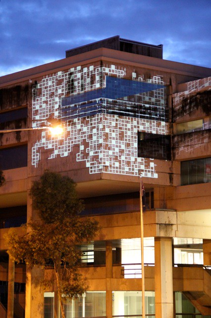
Further variance is introduced by randomly disabling the functions to copy parents and neighbours block states, and to connect streets, as well as varying the grid size (block size), maximum neighbours (density of city development), maximum parents (number of possible streets connections), grow age (speed of new growth and redevelopment), maximum age (age, and therefore size, of city when it is cleared and a new city is generated) and start position/s (city centre/s).

One final small additional benefit of containing growth within a 2d array is that it provides an easy way of setting boundaries to stop the growth going off screen, ie to have a neat edge that avoids cropping. This does not deal with windows - we are hoping that the light projection will be transmitted through the windows and so not seen.
Generic City C6 - all block types and functions enabled, visable emergent neighbourhood patterns 

Generic City C6 - only squares and courtyards enabled

Generic City C6 - twin lanes turned on in N-S orientation, two start positions